One of my favourite elements are LEDs. (light emitting diodes)
The greatest advantage of them: You can see if your project works immediately. But the old fashioned singe-color LEDs are boring and the RGB-LEDs need three different channels (per LED!) of your microcontroller. Another disadvantage of this standard-LEDs is that you need to use PWM to dim them.
The WS2812B solves this issues. They have also four pins but with a different purpose: VCC, GND, data-in and data-out. So you might assume that we can chain them ==> Yes you are right! But it comes even better: You can address every single LED.
So if we assume that we have 8 LEDs you would need 24 channels when you use a standard-LED but still only one channel if you use the WS2812B.
Materialist
- WEMOS D1 mini or any other microcontroller
- WS2812B (8 Bit) or a stripe
- 1000 µF capacitor
- 220 Ω resistor
- Logic Level Converter (I will explain it later on!)
Putting it all together
In the following three subsections you will find some information about basic circuits.
Basic circuit
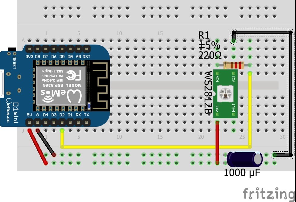
So let's get started. For a basically functioning LED-cluster we need to hook some parts up like this:

As you can see we used the LED-cluster, the capacitor and the resistor in addition to the microcontroller. We need the capacitor because we can change the colours and the brightness in a very high frequency. To "buffer" the resulting differences in the current the datasheet recommends the usage of a capacitor with a value between 100 µF and 1000 µF. Additionally we want to protect the data-pin, what is done by the usage of a 220 Ω resistor.
Ideally you position this two elements as close as possible to the first LED in the cluster.
(The circuit would also work without the capacitor and the resistor. But due to the fact that this elements do not cost much I would recommend to use them as shown.)
Working with 3.3 Volts
If you are using a microcontroller with an operation voltage of 5.0 Volts (e. g.: Arduino Nano, Arduino Mega, etc.) and your only goal is to learn how to use the WS2812B, you can ignore the following excerpt and schematic.
If we have a look at the datasheet of the WS2812B, we will find the definition of the logic HIGH:
VIH = 0.7 * VDD
So what does this mean if we power our cluster with 5.0 V?
5.0 * 0.7 = 3.5 Volts is the minimum to be interpreted as logical HIGH. So there are two possibilities to solve this problem:
- increase VIH (our 3.3 Volts - the operating voltage of our microcontroller)
- decrease VDD (our 5.0 Volts - the operating voltage of our LED-cluster)
The second option (in my opinion a "quick and dirty"-fix) implies an increasing current. Based on this fact I would prefer the first one. And this can be achieved with a logic level converter. This element lets you convert signals between the two levels 3.3 and 5.0 Volts in a bidirectional way. Many of the available modules (for breadbord-usage) have 2, 4 or 8 channels.

(Additional information: A known symptom for this problem is that the first LED in the cluster seems to be "dead".)
Large LED-clusters
If we assume to have a LED-stripe of five metres. If you power it from one end the current has to travel ten metres in total. The difference between the data and the power is that the data has a fixed direction. To reduce the stress of the stripe you can power it in the middle of the strip so that the current has to travel only five metres in each direction.
If you have a very long stripe you can power the stripe at multiple points.
Programming
After all the hardware related text lines we now continue with the software. This paragraph will not be that long, because the documentation on the web is of very high quality.
Adafruit published a great library. This lines of code cover all the basic operations for WS2812B-LEDs.
A few comments to important commands: (variables are wrapped with exclamation marks.)
| Command | Description |
|---|---|
| #include <Adafruit_NeoPixel.h> | Include the library, so that you have access to all the methods. |
| Adafruit_NeoPixel pixels; | Define a variable which represents the LED-cluster. |
| pixels = Adafruit_NeoPixel(!NUMPIXELS!, !PIN!, NEO_GRB + NEO_KHZ800); | This command sets the count of the LEDs, the pin, the datastructure and the speed. |
| pixels.begin(); | Activate the LED-cluster. |
| pixels.setPixelColor(!ROWCOUNT OF THE PIXEL!, pixels.Color(!RED!,!GREEN!,!BLUE!)); | Set the colour of a single LED in the cluster. If you want to set the colour of multiple LEDs, you have to do realize this with a loop. |
| pixels.show(); | If you only set the colour with the previous command, you will not see any changes. |
In some of my projects I wanted to set the colour via an interface. Therefore I wanted to transmit just one value instead of three. After a short code review I found something really interesting. You do not need to use the "pixels.Color"-function, because we can replace it with an uint32_t. The trick is that we have to move the byte for the red value 16 bits left, the value for green 8 bit left and sum all three values. Basically this should be done in your frontend respectively on your controller-site.