As you might have noticed I am currently updating the household with some "smart devices". All of the old 433 MHz actuators have been replaced by WiFi actuators from Sonoff. At the moment I am controlling all the actuators via the web-interface of HomeAssistant. This is basically great, but I do not want to be a slave of my smartphone/tablet/PC. Especially not for such a simple task like turning lights on or off. When I browsed itead I found a "smart switch" - the Sonoff Touch. Seconds later it was on my list of ordered items.

Analysing the switch
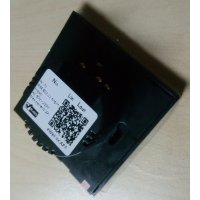
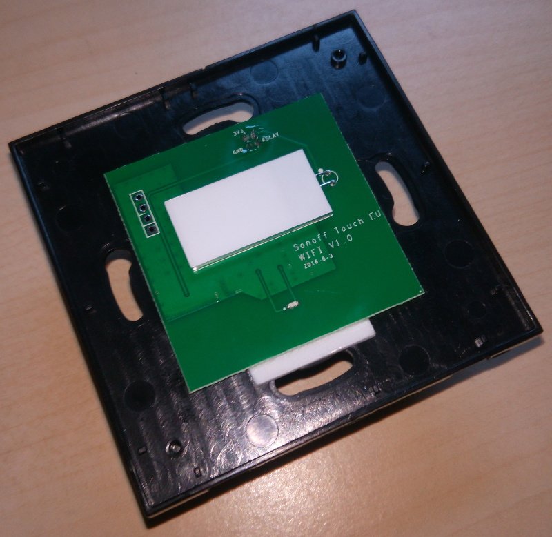
A few weeks later the switch arrived. The first task is to open it and find out if an ESP is used for the WiFi-connectivity.
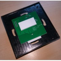
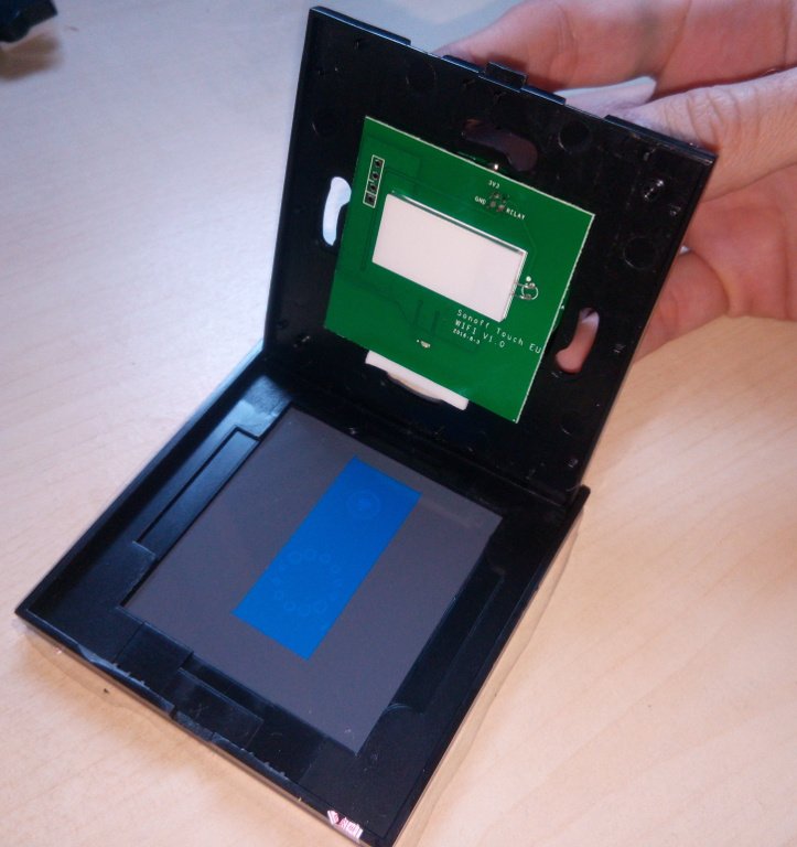
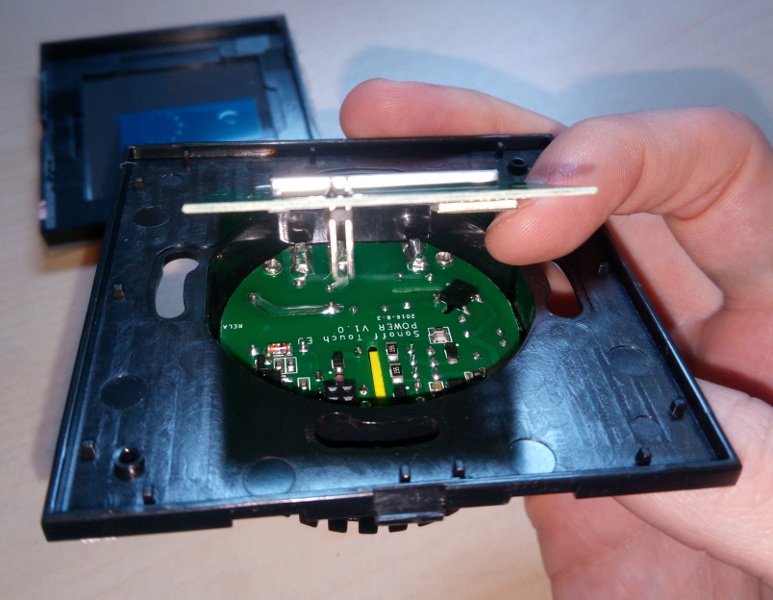
- You need to break the seal and detach the front of the switch.

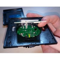
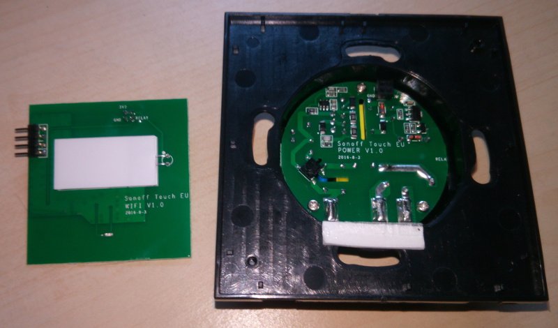
- Remove the sensor-panel from the relay.
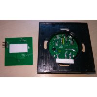
- Check the available pins with your multimeter.
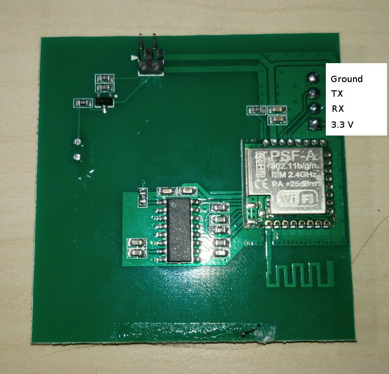
- When you remove the sticker from the µC you can see that it is PSF-A from itead.
As stated on the wikipage the PSF-A is an ESP-8285.
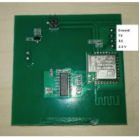
Important: The button is linked with GPIO-0. So you need to hold it during booting up to be able to flash something. - Add some pinheaders to be able to flash a program.
Flashing a program and configuring it.
Before we get into this topic we need some information about the pinmapping of the Sonoff Touch. So here is a small table with the three most important pins (for our desired actions):
| Pin | Mapping | Funcionality | Note |
|---|---|---|---|
| 0 | D3 | Touchbutton | If there is no action the button returns 0. When you touch it it shows a state of 1 for about a second. |
| 12 | D6 | Relay | The backgroundlight for the touchbutton is linked to the relay. |
| 13 | D7 | Connection-LED |
There are multiple possible programs which you can flash onto your Sonoff Touch. The easiest way to customize your switch is to use Sonoff-Tasmota. If you want to have advanced options you can use [espeasy](). I chose espeasy because of it's flexibility. Just connect your switch with your USB-TTL-adaptor and start the flashprogress. It is very important that you choose the correct target-platform. (It may be necessary to deactivate some plugins so that the program shrinks to fit onto the controller.
The flexibility of this program has one disadvantage: the configuration can be confusing. So: Let's get ready to rumble.
Basic configuration
First you need to locate your device in your network. Now you can access the device via your browser. If you want to use your "Connection-LED" as a status indicator you need to switch to the "Hardware"-tab and select "GPIO-13 (D7)" in the dropdown for "Pin LED" and save this configuration. (You do not have to do this! You can also use this LED as a nightlight or an indicator for something else.) In the same tab you can also set the boot state of your relay. Just select the desired option under "Pin mode 12 (D6)" and hit the button to save the settings.
Setting up MQTT
Now we need to setup the MQTT-controller. Therefore we activate the "Controller"-tab and add an entry. You can choose whatever protocol you would like to use. Important note: You can only choose ONE MQTT-format! (I like the notation of OpenHAB.) When everything is activated you can give it a try. For this purpose I am using mqtt-spy. Just append "/gpio/12" to the basic topic the device is listening to and fill the payload with "1". If your switch is assembled you should here the relay clicking.
Confirm actions
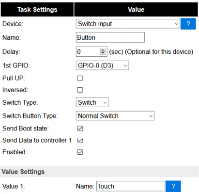
Now it should be working, but there is no response in the mqtt-spy that the relay really changed it's state. So we need to configure something in the "Devices"-tab. You can clone my settings from the following screenshot.

This meets the requirement of some home automation system which otherwise would have to operate in an optimistic way. (They have to assume that the action happens when they send the command/request.)
Linking the button and the relay
The next and final step is to link the button with the relay. To be able to do this we can either use tools like node-RED or we can do it directly on the device itself. The latter one is my preferred solution because it also works if our broker is down. To be able to achieve this we need to activate the "Rules" in the "Advanced"-section of the "Tools"-tab. Now you should see a "Rules"-tab. Here we can paste the following code and save it:
On Button#Touch=0 do
    if [gpio#12/state]=0
        gpio,12,1
    else
        gpio,12,0
    endif
endon
For now it will not do much because the trigger "Button#Touch" is not defined. We need to switch to the "Devices"-tab and configure another one like in the following screenshot.